banner


How Clean The Hp 3520 Printhead Using What Is Included In The Printer?

Introduction

This guide provides management on cleaning the print-head in your HP DeskJet 3524 printer. The print-head is the mechanism which transfers ink onto the paper. The HP DeskJet 3524 user manual also provides boosted directions for cleaning the impress-head.

  1. Power on the printer. To access the cartridge door, locate the two tabs on the left and right side of the printer. Lift up on the tabs  and the print wagon will move into the access area. After the wagon is accessible, the print-head will center itself in the printer.  Once it is centered, remove the ink cartridges. To do this, press on the front tab of each cartridge. After the cartridges are removed, wrap them in a paper towel and set them  to the side.

    • Ability on the printer.

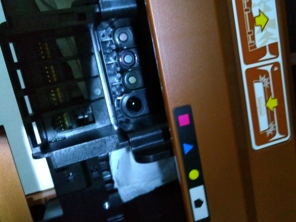
    • To admission the cartridge door, locate the two tabs on the left and right side of the printer. Lift up on the tabs and the impress wagon volition move into the admission surface area.

    • Afterwards the wagon is attainable, the print-head will heart itself in the printer. One time it is centered, remove the ink cartridges. To do this, press on the front tab of each cartridge. After the cartridges are removed, wrap them in a paper towel and gear up them to the side.

    • With the impress-head withal accessible in the center, power off the printer and unplug the machine.

  2. Next,  apply pressure on the "clean out door." The door will loosen and allow removal. Next,  apply pressure on the "clean out door." The door will loosen and allow removal.

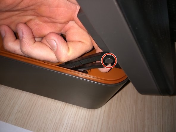
    • Next, utilise pressure on the "make clean out door." The door will loosen and allow removal.

  3. Next, locate the seven torx screws (highlighted in red circles).  To avoid confusion when reassembling later, we suggest drawing a picture of the printer and taping the screws to the image. After removing the seven screws, loosen the lever from the scanner compartment.

    • Side by side, locate the seven torx screws (highlighted in ruby circles). To avoid confusion when reassembling later, we suggest drawing a moving picture of the printer and taping the screws to the image.

    • After removing the vii screws, loosen the lever from the scanner compartment.

  4. Next, remove the orange cover. Use caution as the display unit is still attached to the cover. If you pull the cover off too quickly, you could tear the flat cable. In the second and third pictures, you will see 2 black plastic buttons. Push on the buttons and the display unit will separate from the orange cover. When reassembling, ensure the white flat ribbon cable is correctly attached. If it is not attached correctly, you will be unable to push the orange cover closed.

    • Next, remove the orangish cover. Employ caution equally the display unit of measurement is still attached to the embrace. If you lot pull the cover off too quickly, you could tear the flat cable.

    • In the 2d and third pictures, you lot volition run into 2 black plastic buttons. Push button on the buttons and the brandish unit of measurement will separate from the orange comprehend.

    • When reassembling, ensure the white flat ribbon cablevision is correctly attached. If it is not attached correctly, you will be unable to push the orange cover closed.

  5. Next, locate the 2 iron springs and remove with pliers.

    • Next, locate the 2 iron springs and remove with pliers.

    • Later on removing the springs, gently remove the print-head, but not completely as the print-head is withal fastened to the printed circuit board (PCB).

  6. The printed circuit board (PCB) is the flat green object perpendicular to the printer. Gently remove the PCB by unscrewing the two torx screws (highlighted in red circles). Prepare to remove the flat cables attached to the PCB. They are also connected to the print-head.

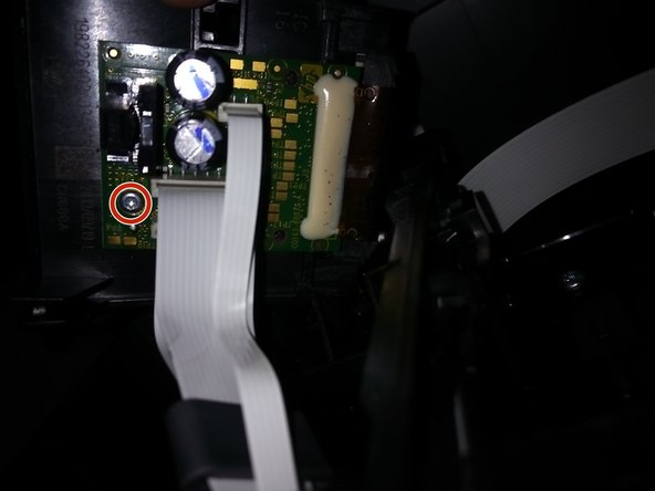
    • The printed excursion board (PCB) is the apartment green object perpendicular to the printer.

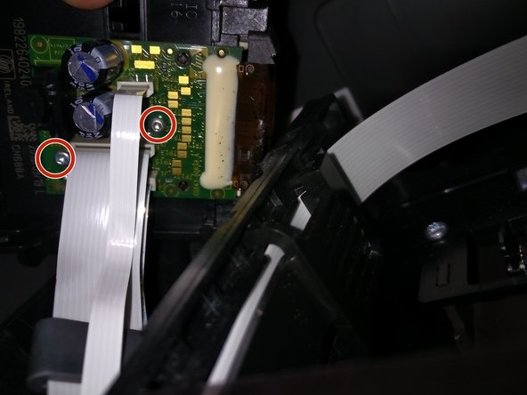
    • Gently remove the PCB by unscrewing the two torx screws (highlighted in carmine circles).

    • Ready to remove the flat cables attached to the PCB. They are also connected to the impress-head.

  7. There are 2 flat cables. To avoid confusion when reassembling, mark one to ensure the cables are correctly matched  to the socket. After making the necessary markers, gently pull the flat cables away from the socket.

    • There are 2 flat cables. To avoid confusion when reassembling, marker one to ensure the cables are correctly matched to the socket.

    • Later making the necessary markers, gently pull the flat cables away from the socket.

  8. Because the next steps involve water, we suggest cleaning the print-head over the sink. Before you begin, gather the following: 2 bowls of water (one with distilled water and one with regular water), cotton swabs, syringe, and paper towels. Fill the syringe with distilled water and spray the small holes on the print-head. Use the cotton swabs to  scrub and clean the crevices. Please note: You will only use the distilled water to clean the device. The regular bowl of water is used for cleaning the syringe.

    • Because the next steps involve water, we advise cleaning the print-caput over the sink. Before you begin, assemble the following: 2 bowls of water (one with distilled h2o and 1 with regular water), cotton fiber swabs, syringe, and paper towels.

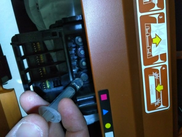
    • Fill the syringe with distilled h2o and spray the minor holes on the print-head. Use the cotton swabs to scrub and clean the crevices.

    • Please notation: You will only use the distilled h2o to clean the device. The regular bowl of water is used for cleaning the syringe.

  9. Please note: It is important that you do not spill distilled water or regular water on the PCB. Use a cotton swab to clean around  the PCB. If you spill any water on the PCB, immediately clean the PCB with isopropyl alcohol. After cleaning the print-head, allow the device to air dry for a few hours.

    • Please note: It is important that you do not spill distilled water or regular water on the PCB. Use a cotton fiber swab to clean around the PCB.

    • If you spill any water on the PCB, immediately make clean the PCB with isopropyl alcohol.

    • Subsequently cleaning the print-head, permit the device to air dry out for a few hours.

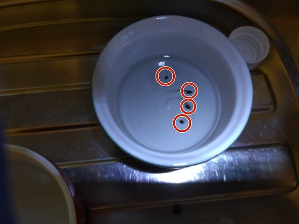
    • In the last motion-picture show, you lot will see 4 black spots in the water. That is hard, dried ink which caused my printing problem.

  10. When reassembling the print-head, ensure the black lint is under the black connector (see photo). If the blink lint is above the connector, you will receive a "wagon error" code. The wagon will essentially hit the right side of the printer, unable to go tot he left side. After the printer is reassembled, print an "alignment page" and a "cleaning print head page."

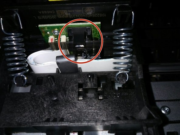
    • When reassembling the print-caput, ensure the black lint is under the black connector (see photograph). If the blink lint is to a higher place the connector, you lot will receive a "carriage mistake" code. The wagon will essentially hit the right side of the printer, unable to go tot he left side.

    • After the printer is reassembled, print an "alignment page" and a "cleaning impress head page."

Conclusion

To reassemble your device, follow these instructions in reverse order.

Embed this guide

Choose a size and re-create the code below to embed this guide as a small widget on your site / forum.

Preview

Source: https://www.ifixit.com/Guide/How+to+Clean+the+HP+DeskJet+3524+Printhead/76119

Posted by: standleysaided.blogspot.com

0 Response to "How Clean The Hp 3520 Printhead Using What Is Included In The Printer?"

Post a Comment

Iklan Atas Artikel

Iklan Tengah Artikel 1

Iklan Tengah Artikel 2

Iklan Bawah Artikel